)%20(1920%20%C3%97%20540%20px).png)
A Tour Inside a Network Setup of a VFD Drilling Rig
- Abdelrahman Shaker
- Aug 5, 2024
- 5 min read
Welcome to my blog, where I share insights and knowledge about working as a senior electrician on a drilling rig. Recently, I had the opportunity to join a new rig during its project phase, a cutting-edge setup manufactured by the Egyptian-Chinese company EPHH. This rig is equipped with some of the most advanced technologies in the industry, designed to enhance efficiency and reliability in drilling operations. In this post, I will delve into the electrical system of this modern rig, with a particular focus on its network setup. Whether you're an experienced rig electrician or just starting in the field, I hope this detailed overview will expand your understanding and help you navigate the complexities of rig electrical systems.
Introduction
In this article, we will use a diagram of the rig network to make it easier to understand how the network system on the rig works. We will look at each part separately to show how they are connected to each other.
If you need to download this diagram, press here to be redirected to the PDF file.

There are three main areas in this network:
1. VFD House: This is the main electrical room on the rig. It supplies power to all rig equipment and contains the PLC (Programmable Logic Controller), VFDs (Variable Frequency Drives) for all motors, and generator control cubicles. It is the central hub where equipment control takes place.
2. Power House: This area houses the engines and generators, making it the primary source of power for the rig.
3. Rig Floor: The rig floor is the primary working area on a drilling rig where key drilling operations occur. It includes essential equipment such as the Drawworks and top drive. It also features the driller’s cabinet, which contains monitors for the driller (operator) to manage and operate all equipment.
If you are new to this field, I recommend reading my article, “A Beginner’s Guide to Being an Electrician on Drilling Rigs,” available here:
PROFINET Network

The entire network on the rig relies on PROFINET connections. All devices, including PLCs, VFDs, HMIs, PCs, and the HPU, are interconnected through PROFINET cables. This ensures fast, reliable communication across the network, enabling real-time monitoring and control of all equipment. PROFINET’s robust and flexible nature makes it ideal for managing the complex and demanding operations on the rig. I will discuss PROFINET further in future blog posts to provide more detailed insights into its capabilities and benefits.
Ethernet Switches

One thing you'll notice in the network diagram is that there are ethernet switches (MOXA) in both the VFD house and the Driller’s Cabinet.
Ethernet switches play an important role in connecting all devices, such as PLCs, VFDs, HMIs, the PC, and the HPU. These switches manage and direct data traffic, ensuring that information flows efficiently and reliably between the various components, which is crucial for real-time monitoring and control of the rig’s operations. They also help keep the network organized and secure.
PLC
Inside the VFD house, there is a PLC responsible for controlling and monitoring the entire network, including generators, sensors, drives, HMIs, and more.
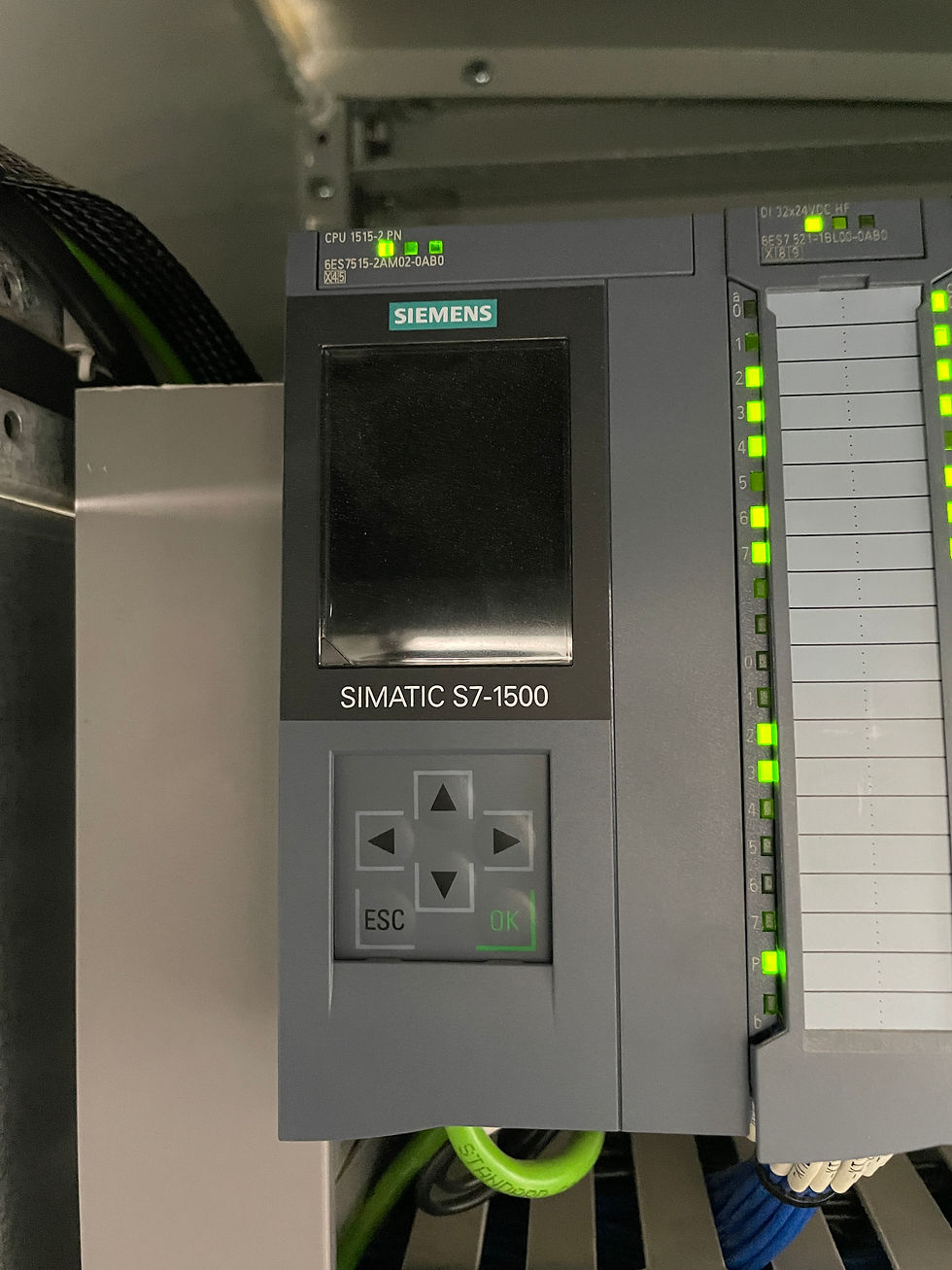
On this rig, the PLC is a Siemens SIMATIC S7-1500, which is divided into two racks:
1. Main Rack: Located in the VFD house, it includes the power supply, CPU, and signal modules.
2. Extension Rack: Located in the driller’s cabinet, it includes the power supply, interface module (SIMATIC ET 200MP), and signal modules.
The CPU and interface module are connected to the Ethernet switches through a PROFINET cable, allowing the PLC racks to communicate with each other and with other devices on the network, such as HMIs, VFDs, PCs, and other control units.
Engines and Generators
Engines and generators on a drilling rig are crucial components that provide the necessary power to operate all the equipment and systems. Engines used on the rig are 3 engines of model CAT 3512B type engines, Each supplies 995 KW.
Engines are very critical equipment, so it is very important to keep it working continuously and this is one of the main responsibilities of maintenance team. For this reason, connecting engines to the PLC is essential for efficient monitoring and control.
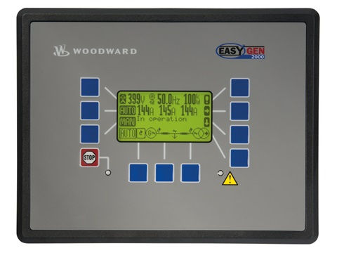
Inside VFD, there are 2 bus adapters responsible for communication between engines and PLC. One of them (C1) is the communication between PLC CPU and a device called Woodward easYgen which is an advanced genset control unit designed for efficient load sharing and power management across multiple generator sets.
The other one (C2) is the communication between PLC and control panel on the engine inside power house.
Both C1 and C2 are connected to PLC via PROFINET network and with engines and easYgen via MODBUS network
By linking engines with PLC, we can achieve the following:
1. Monitoring: Track engine performance metrics such as Current, KW, power limit, and operational status.
2. Warning and Faults: Receive alerts for any abnormal conditions on HMIs, allowing for quick response to potential problem
3. Data Logging and Analysis: Collect and analyze performance data to optimize engine operations and maintenance schedules.
Variable Frequency Drives (VFD)
Another important system connected to our network is the VFD (Variable Frequency Drive). The VFD system controls AC motors, and since all motors on the rig are AC, we have a VFD for each motor. Our rig uses the ABB ACS880, the latest drive technology from ABB and one of the most popular in the drilling industry.
These VFD systems are connected to the PLC via a PROFINET cable that runs from the MOXA Ethernet switch to a device called the PROFINET IO adapter (ABB FPNO-21). This adapter provides fieldbus connectivity for ABB drives. The FPNO-21 then connects to the BCU board, which manages the inverters via fiber optic links.
If you want to learn more about VFDs, you can read my article on the fundamentals from here:
HMI
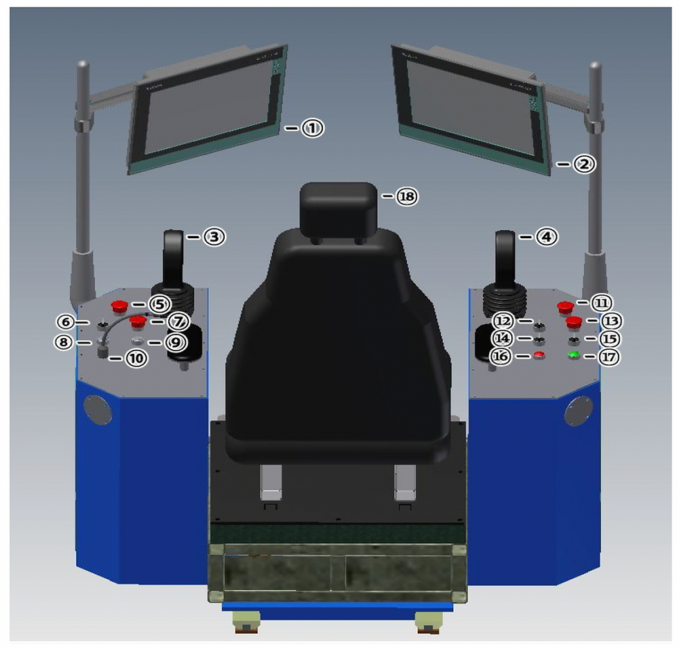
The driller's cabinet contains 2 HMIs that are integral to the driller's control system. These HMIs are positioned on the right and left sides of the driller, as illustrated in the following photo (labeled as numbers 1 and 2).
Through the HMIs, the driller can control the trip in/out, drilling operations, mud pump, HPU, in addition to monitoring and adjusting drilling parameters.
Hydraulic Power Unit (HPU)
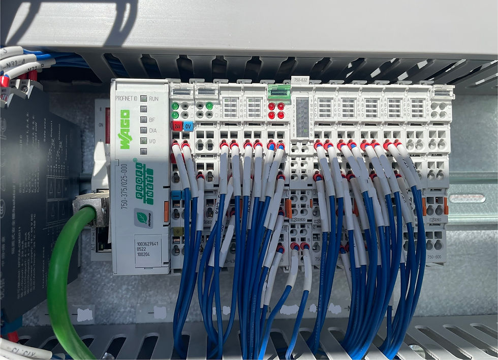
The Hydraulic Power Unit (HPU) installed on a drilling rig is a system that supplies hydraulic power to different equipment. It includes motors, hydraulic pumps, control valves and more. HPU on this rig is controlled by a WAGO I/O system that consists of digital and analog modules linked to all signals on the HPU. This WAGO system is connected to the PLC within the Driller's cabinet via a profinet cable running from the WAGO system's CPU to the ethernet switch inside the driller's cabinet.
Thank you for joining me on this tour inside my rig's network setup. I hope this detailed overview has given you a better understanding of how the various components work together to ensure smooth and efficient operations. From the VFD house and power house to the rig floor, each part plays a crucial role in maintaining the rig's performance. Stay tuned for future posts where I will delve deeper into specific systems and technologies. Your feedback and questions are always welcome, so feel free to leave a comment or reach out. Until next time, keep exploring and learning!


Comments